Tongue pressure detection
Demo
Vid. 2 Map a traditional keyboard onto a touch area and integrate a swipe input algorithm to enable typing with the tongue.
Project Objective
In this project, we aimed to construct a wearable tongue-controlled input system. I collaborated with Meiling Liu, who developed LIG pressure sensors and apply the whole system, and Weihao Chen, who managed array data analysis and the tongue-controlled input software. My responsibilities included hardware programming and the development of BLE communication. I will now provide an overview of my contributions in the following sections.
System architecture
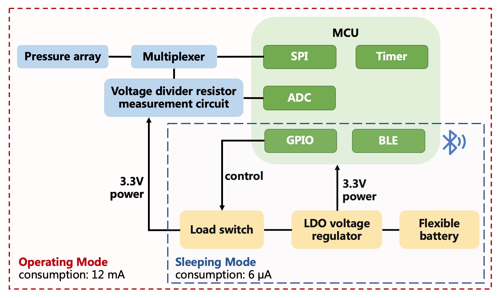
The wearable tongue-controlled device mainly includes 3 modules:
- MCU module to control the operation flow and transmit BLE signal.
- Power management module to regulate the voltage, control the power consumption and support wireless charging.
- Pressure array resistance detection module which can measure the resistance of 148 pressure sensors.
 Fig. 1 System architecture. The green part represents MCU module; The yellow part represents power management module. The blue part represents pressure array resistance detection module.
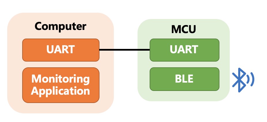
The receiving terminal consists of PC and nRF52832 board to receive, display and process the ECG data.
 Fig. 2 The receiving terminal
Hardware
ADG725 is a dual 16-channel analog multiplexers with a SPI interface. I used ADG725 to implement row and column switching, scanning the entire pressure array using time-division multiplexing.
nRF52832 MCU
- Use the ‘successive-approximation ADC’ to convert analog data with 12-bit resolution (0.878 mV).
- Set the timer, compare event and PPI to sample per 25 μs.
- Declare service, characteristic and handles. Every time after sampling 148 times, compress data at the bit level, encapsulate a BLE packet and update the characteristic value to transmit resistance of the pressure array to the master.
- Sleeping mode: Set BLE slave’s advertising interval 5 s and disable all peripheral functions to decrease power consumption, and the current consumption is about 6 μA.
- Operating mode: When the BLE slave is scanned and connected by a master, pull up the GPIO which controls the load switch, then the load circuit can be powered. Also enable ADC and timer, then start to collect and transmit data. The current consumption is about 12 mA.
- Power Management
- Use TPS7A022 to regulate voltage to 3.3 V
- Use TPS22919DCKR as load switch to control the power supply for load circuit.
 Fig. 3 (a) Dental retainer after encapsulating the FPC circuit; (b) The device is placed inside the oral cavity; (c) The dental retainer is barely visible in daily situation
Achievement
[Under Review] Meiling Liu, Rongzan Lin, Weihao Chen, Zhe He, Xinxin Mao, Yongjie Feng, Weinan Shi, Xinming Qiu, Chun Yu and Ran Liu. A high–performance tongue–computer interface.
